

Bent-wire supports inserted into a pallet may look alike while working differently. In its judgment of 7 October 2026 in case 2026 Heo 10080, Korea’s Patent Court examined which parts provided support, the forces involved and how the parts worked together. It held that the two defined target inventions fell outside the respective patent claims.
Two defined support assemblies were compared with claims 1 and 4
The defendant, Seongu Rotech Co., Ltd., held Korean Patent No. 1548268 for a cargo support for a grid-type cargo pallet, filed on 18 July 2014 and registered on 24 August 2015. The pallet has intersecting longitudinal and transverse frames; a wire support is inserted into it to restrain sideways cargo movement.
The plaintiff, Sanho PNL Co., Ltd., sought a negative confirmation of scope: a ruling that target invention 1 fell outside claim 1 and target invention 2 outside claim 4. A target invention is the technology defined by the description and drawings submitted for comparison; a claim defines the patented subject matter.
The Intellectual Property Trial and Appeal Board (IPTAB) rejected the petition on 10 February 2026 in case 2025 Dang 3175. The plaintiff sought annulment. The court compared claims 1 and 4 with the target inventions as amended on 29 January 2026.
The decisive limitation was at the end of the wire
Claim 1 and target invention 1 shared several undisputed features: a multiply bent wire, a horizontal portion supporting the cargo, downward vertical portions and two insertion portions fitted into holes in the pallet frame.
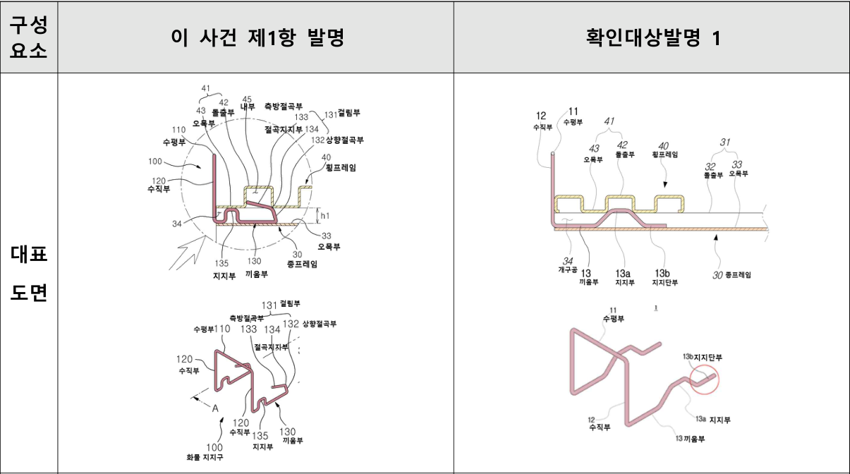
The dispute concerned claim 1’s sixth element, a catch formed by bending the end of the insertion portion upward and supporting it against the inside of a projection on the transverse frame crossing above. Bending describes forming an angle in the wire or other material.
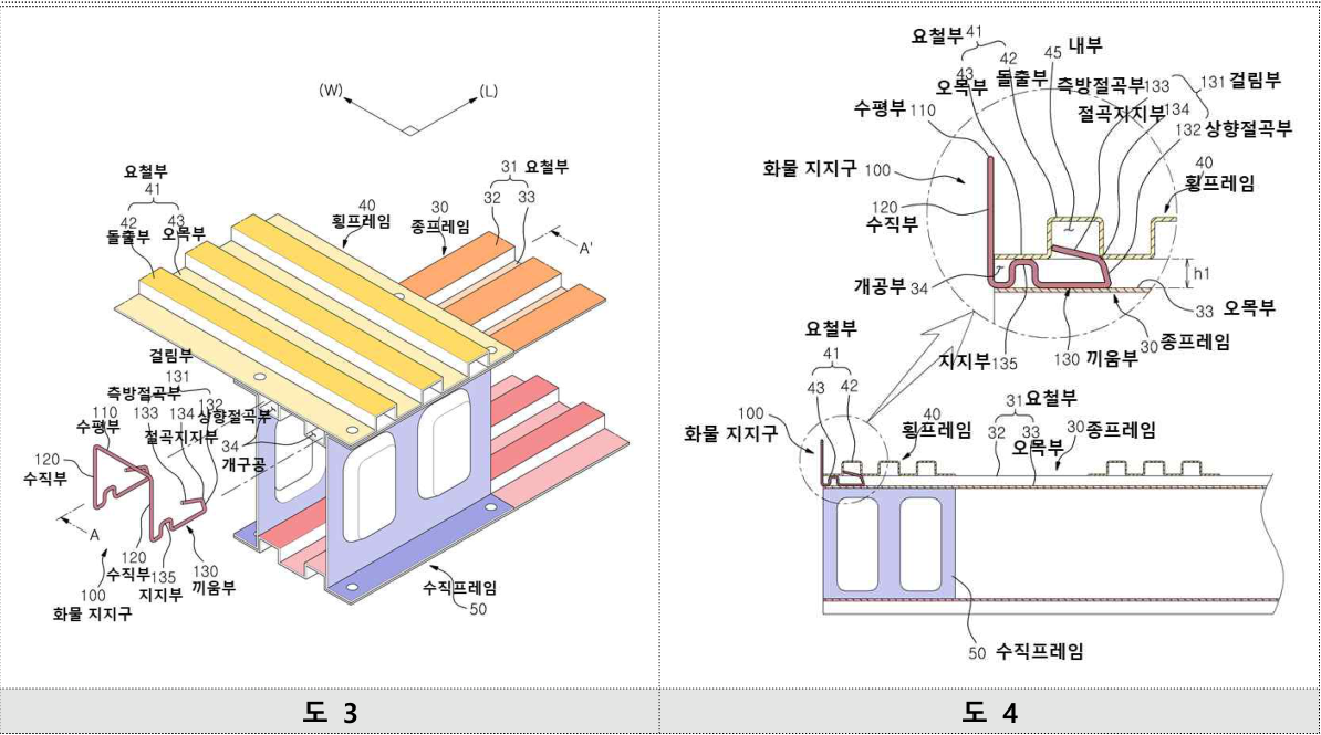
The court interpreted the catch as providing sufficient restraint against sideways cargo movement through the elasticity and rigidity arising from that contact alone. Elastic force tends to restore a deformed member; rigidity is its resistance to bending or deformation under load.
An upward bend could coexist with horizontal and downward bends
The plaintiff argued that a shape with additional horizontal or downward bends should be excluded. The patentee maintained that such additional shapes were permitted if an upwardly bent portion was present.
The court accepted that upward, horizontal and downward portions could coexist. Neither the claim nor the description required the wire to bend only upward throughout. A trapezoidal shape rising, running horizontally and descending was therefore not excluded merely because of its outline.
But the presence of an upward bend was not enough. Reading the claim in light of the description and drawings, the court required the inside contact to provide the necessary support by itself. The operative support mechanism mattered more than the label given to the bending direction.
Target invention 1 relied on both portions 13a and 13b
Support portion 13a formed a trapezoid taller than the hole’s internal height. It deformed elastically during insertion and recovered once inside. Terminal portion 13b extended from it and pressed against the floor of the recessed frame.
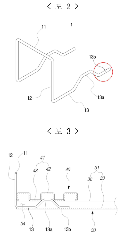
The two portions worked together: interference fitting generated a restoring force, while friction at the contact surfaces resisted vertical movement and stabilized the assembly. Friction is the force opposing sliding between contacting surfaces.
The patentee equated 13a with the claimed catch because it bent upward and contacted the projection’s interior. The court’s analysis of comparative examples 1 and 2 showed that 13a alone did not generate the necessary elasticity and rigidity, or generated too little to restrain the cargo. The necessary support arose only with 13b. Isolating 13a could not establish the claimed element, so target invention 1 was outside claim 1’s literal scope.
The different operating principle and effect also defeated equivalence
A changed feature may still be equivalent if the applicable legal requirements establish substantially the same technical means. Here the court considered the problem-solving principle and operating effect. Bent-wire elastic fitting and stopper-and-ledge fixing were already known. Against that background, it identified the patent’s particular core as a catch supported inside the projection, securing the assembly through its elasticity and rigidity alone.
Target invention 1 instead required the connected operation of 13a and 13b, combining pressure from elastic recovery with contact friction. The court found a different problem-solving principle. It also found a different removal effect: the patented catch required force causing permanent plastic deformation and was difficult to regard as reusable, whereas the target passed through the hole by elastic deformation and was easier to detach and reuse.
Because both the specific principle and effect differed, the court rejected equivalence without further examining whether the change would have been easy for a skilled person to devise. A shared purpose of supporting cargo did not make the mechanisms equivalent.
Adding an end portion did not establish a dependent invention
The patentee also argued that target invention 1 retained the patented arrangement and merely added 13b. A dependent invention, in this context, retains and uses the earlier patent’s constituent elements and their interrelationship while adding a new technical element.
That argument failed because 13a could not perform the patented catch’s function alone and required 13b. The court therefore did not find all the patented elements and their operative combination preserved beneath a simple addition.
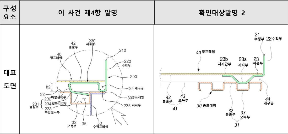
For claim 4, the catch bent downward against the inside of a recess in the longitudinal frame. Target invention 2 used a downward support and a terminal portion contacting the ceiling of the transverse-frame projection. For the same reasons, the court rejected literal coverage, equivalence and the dependent-invention argument. Target 1 was outside claim 1 and target 2 outside claim 4; the court annulled the contrary IPTAB decision of 10 February 2026. The conclusion concerned those defined targets and claims.
Document how the components actually provide support
A scope analysis should ask not only whether a similar component is present, but whether that component alone performs the function required by the claim. If it operates only with another part, document the connection, forces, installation and removal.
For a design change, merely pointing to an added component is insufficient. Explain whether the original elements and their relationship remain intact, or whether the operating principle and effect have changed. These are practical lessons from the court’s reasoning in this case.
The judgment illustrates how detailed assembly mechanics can determine scope despite a common bent-wire support concept. Keep literal construction, equivalence and use of the patented combination as separate analytical steps, identifying the features and effects compared at each stage.
The original figure labels and forms are preserved; the text explains the source material.