

The corrected claim before the court
On July 8, 2026, Korea’s Patent Court decided case 2025Heo10615 concerning radiator patent 1855635, filed December 22, 2017 and registered April 30, 2018. The dispute concerned connections between the radiator body and the header tanks that collect or distribute fluid.
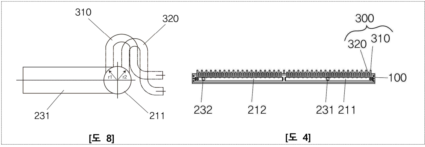
The invalidity petition was filed on January 17, 2025. A correction requested on April 1 deleted claims 2 and 3, leaving corrected claim 1. The court reviewed the IPTAB’s October 31, 2025 decision in 2025Dang157 rejecting the petition. Claim 1 alternated two differently shaped and sized connectors, each with three integral tube portions, at different radial directions around the tank. The first connector lay in a radial direction relatively closer to the inlet or outlet.
Different tube shapes did not establish a different effect
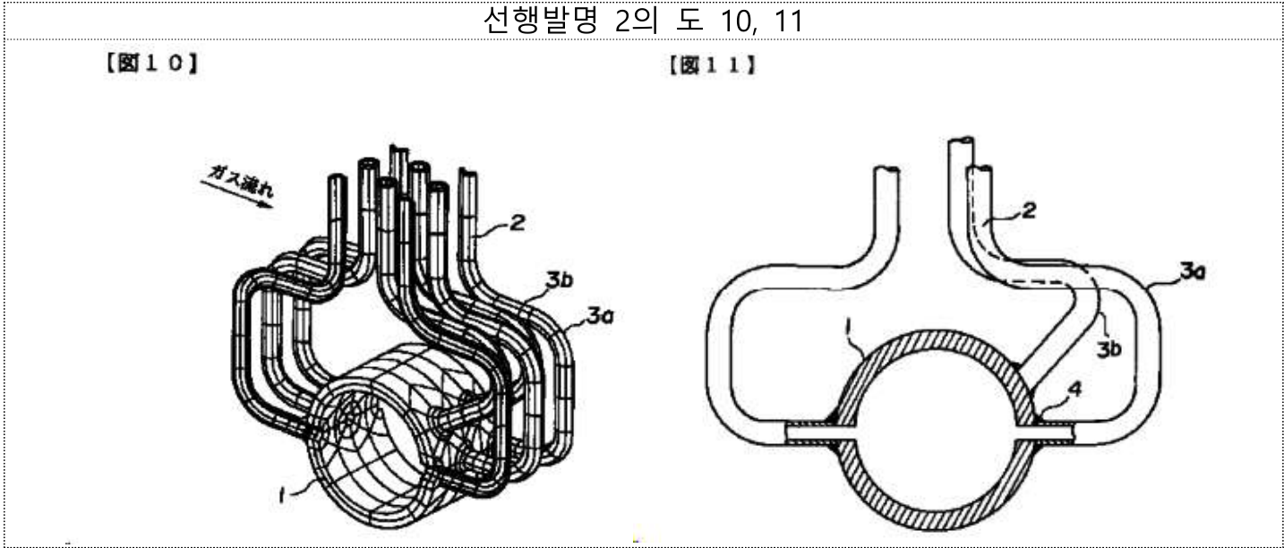
Prior invention 2, a Japanese publication of October 21, 1997 on header-to-heat-transfer-tube joints, described conventional U-shaped and V-shaped bends. The proprietor argued that these were parts of the heat-transfer tubes, not separate connectors. The claim, however, did not require a separately manufactured connector: an integral bend could perform the claimed function.
The court acknowledged the difference between perpendicular and partly parallel tube portions and the oblique V-shaped arrangement. But the stated benefits of a longer fluid path, reduced flow resistance and improved durability were also associated with the known bends. Reduced interference and greater exposed space followed from alternating radial positions, rather than the particular geometric differences.
The prior document used V-shaped bends to facilitate joining or welding where tubes were closely spaced. Offsetting the joint positions could address that difficulty without making a V shape indispensable. U-shaped bends were both conventional and disclosed in the same document, so adopting that alternative did not present the asserted technical difficulty.
Relative placement requires a defined reference
A further difference placed the first connector radially closer to the inlet or outlet. In the illustrated embodiment, those ports lay opposite the radiator body. The first connector’s end was therefore visible from the side while the second was hidden. Yet claim 1 did not specify where, or in which direction, the ports were positioned on the tank.
The relationship could change if the ports were on the body side. The court would not import the drawing’s particular arrangement into the broader claim. Neither the specification nor the evidence identified a technical effect attributable to the visible or hidden ends. The prior document also showed the corresponding offset from the body, although it did not depict the ports.
Choosing port positions to suit the heat exchanger’s structure and manufacture, including a position radially nearer the first connector, was considered straightforward. No meaningful difference in operation or effect supported that selection.
The outcome concerned corrected claim 1
The court assessed the combination as a whole and its effects, rather than merely asking whether each component was known. It nevertheless concluded that a skilled person could arrive at the corrected invention from prior invention 2. It held that the patent should be invalidated for lack of inventive step and cancelled the contrary IPTAB decision.
The decision was not a separate assessment of deleted claims 2 and 3. Although the claimant also advanced novelty and earlier-application arguments, the dispositive reasoning rested on inventive step over prior invention 2; those other grounds should not be presented as additional holdings.
Draft the positional limitation and its effect together
For a positional feature, identify the reference structure and explain how the claimed relationship produces the asserted benefit. A drawing may depict an arrangement more specific than the claim. General advantages of bent tubes or alternating connections do not, by themselves, explain why the distinguishing geometry matters.
This judgment does not establish that small geometric changes are invariably unpatentable. It illustrates the need to address the actual differences, the ease of making the modification and the effects supported across the claimed arrangement.
The original figure labels and forms are preserved; the text explains the source material.