

An improved installation method does not necessarily distinguish a product claim if the completed structure remains the same. In its judgment of 25 June 2026 in case 2025Heo10489, the Korean Patent Court compared a fire-resistant stair railing with an earlier adjustable wrought-iron railing.
The claimed railing and the refusal
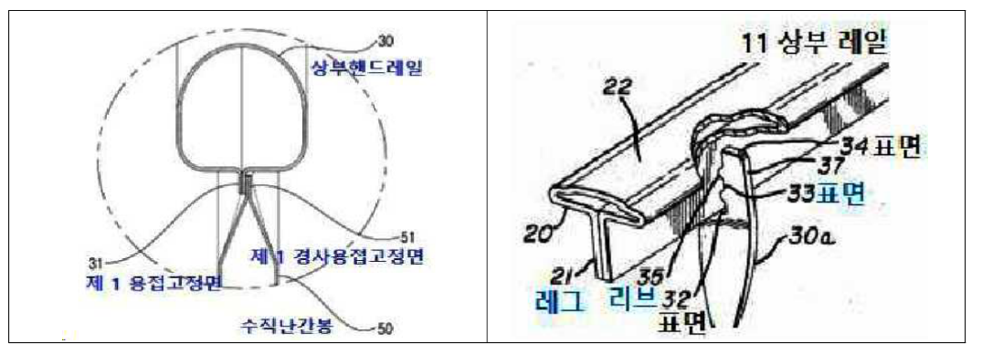
The divisional application, filed on 24 January 2024, described upper and lower upright posts, an inclined handrail and lower rail, vertical balusters and metal end connectors. Claim 1 included a longitudinal projecting welding surface beneath the handrail contacting an inclined surface at the top of each baluster. The stated benefits were easier assembly without separate nuts and bolts, reduced corrosion and retention of the handrail in a fire.
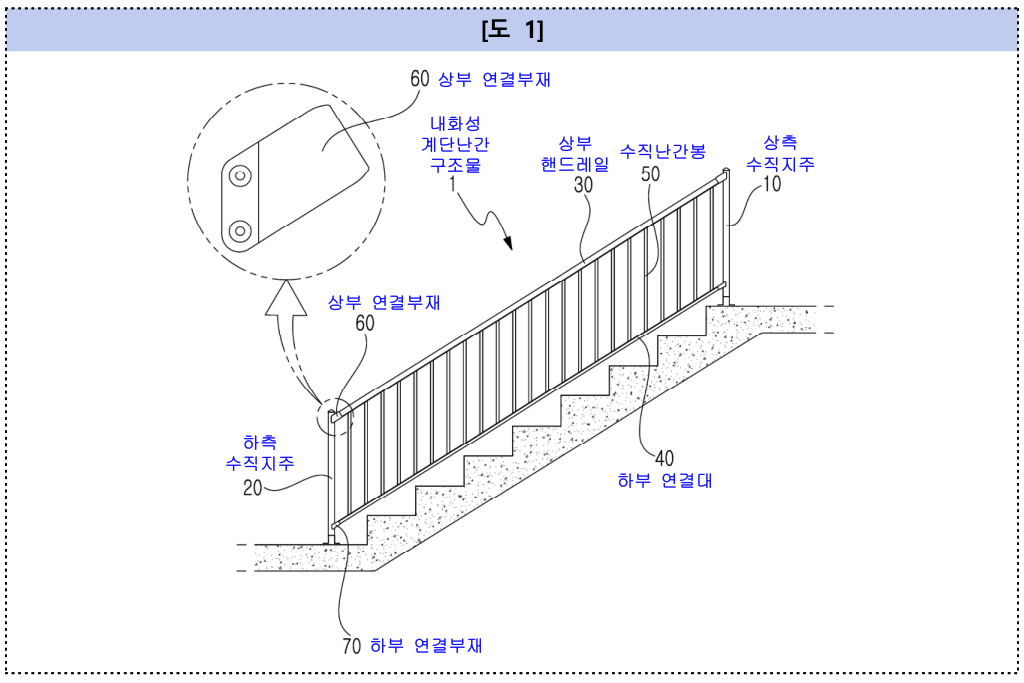
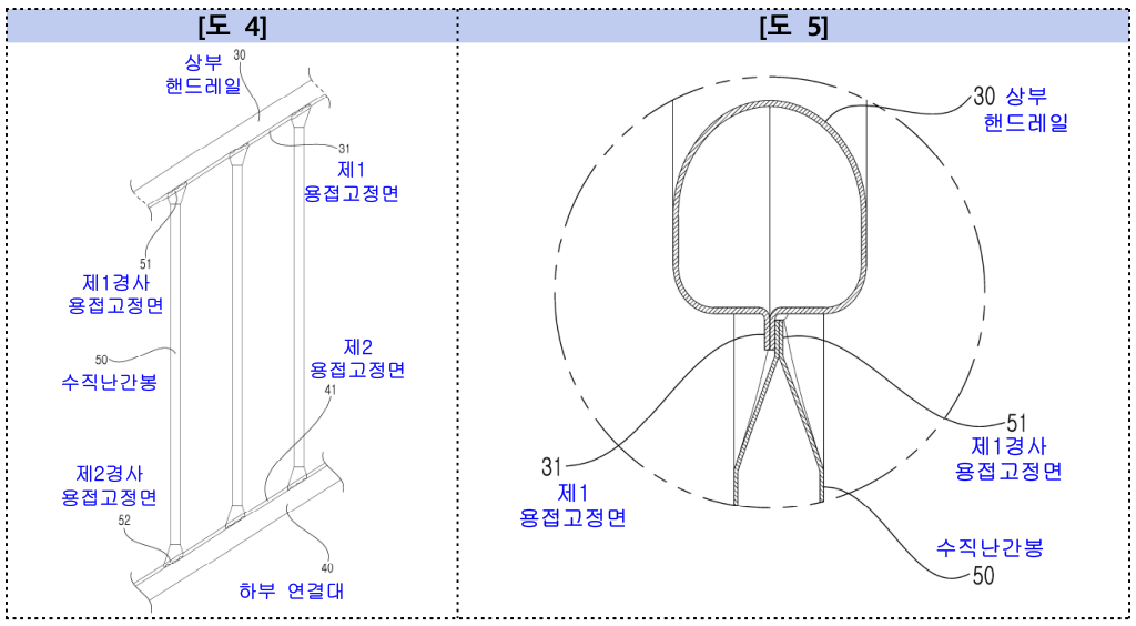
The examiner refused the application on 30 December 2024. Following dismissal of appeal 2025Won587, the applicant sought annulment. The principal reference was US3339895, published in 1967, concerning an adjustable wrought-iron railing.
Manufacturing sequence was not a claim limitation
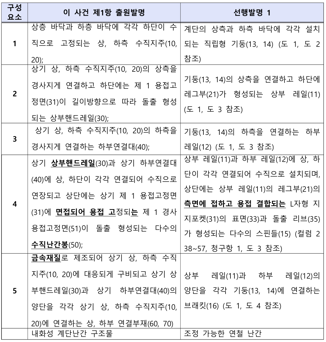
The applicant distinguished its pre-set inclination from the earlier railing, whose angle could be adjusted during installation before attachment to the upright posts. Claim 1, however, required only inclined rails between the posts. It did not specify when the inclination was established or exclude on-site adjustment.
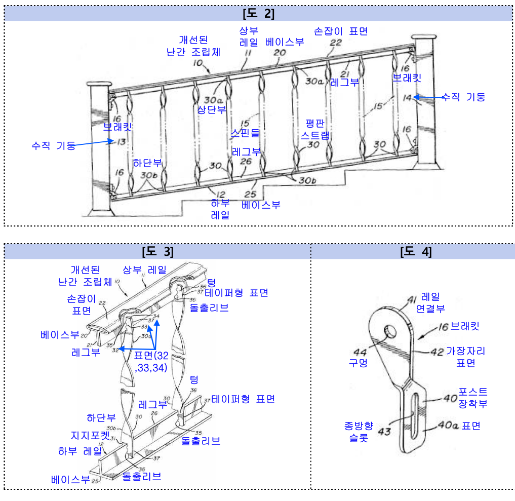
The court compared the completed products. Once the earlier railing was adjusted and installed, its upper and lower rails likewise connected the upright posts at an incline. A different assembly sequence did not establish a structural difference absent corresponding claim language.
The breadth of the welded-contact limitation
The applicant contrasted local welding at a small projection with face-to-face contact welded at multiple points. Claim 1 did not limit contact area, direction, welding technique or number of weld points. Partial surface contact therefore fell within its wording. The specification’s preferred multipoint spot welding did not narrow the claim to that embodiment.
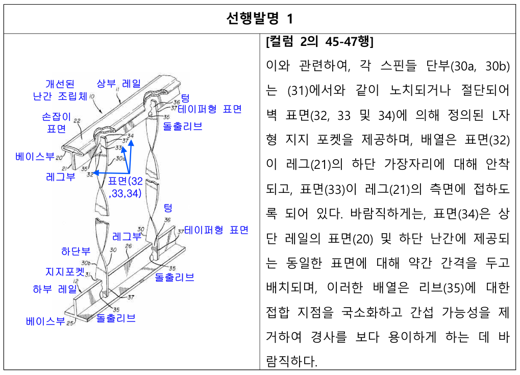
In the earlier railing, a face and projecting rib of an L-shaped support pocket at the baluster end contacted and were welded to the side of the upper rail’s projecting leg. The court considered this substantially the same contact arrangement; any contact-area adjustment would be an ordinary design choice without particular technical difficulty.
Increasing contact area also did not necessarily prevent angle adjustment. In the reference, deformation occurred at a narrow flexible tongue, rather than at the contact surface itself. A larger welded surface did not eliminate that flexibility.
Metal connectors and predictable effects
The earlier reference did not expressly identify the bracket material. Yet choosing metal brackets to connect the main components of a wrought-iron railing was readily available to the skilled person. Easier assembly, corrosion protection and fire retention were considered predictable effects of welded metal rails and metal connections, rather than effects different in kind.
Claim 1 was therefore obvious over the reference, and the action to annul the Board’s decision was dismissed. Because a remaining refusal ground in one claim could justify refusal of the application as a whole, the court did not separately assess inventive step in claims 2–10.
Draft the structural difference that produces the effect
Before relying on a different installation process, identify what difference remains in the finished product. The contact geometry and assembly relationships that matter should be supported by the drawings and reflected in the claims.
If welding conditions or material properties produce the benefit, describe them concretely and consider corresponding limitations. Comparative evidence is most useful when it connects the observed effect to the particular feature claimed. An intended improvement and the structure that delivers it are separate matters.
The original figure labels and forms are preserved; the text explains the source material.